Choosing China’s best Hydraulic Regulation Joystick supplier is not a simple ranking exercise. The right choice depends on the machine, valve interface, operating environment, and service expectations. A joystick may look compact on a desk, yet its signal must remain predictable through repeated movements, vibration, and temperature changes. Small details matter.
Hydraulic systems author Herbert E. Merritt provides a useful technical reference. A practical paraphrase of his systems-oriented approach is: “Control performance depends on how the components work together, not on one component alone.” This is a paraphrase, not a verbatim quotation. It offers a sound starting point for supplier evaluation. Ask for dimensional drawings, electrical output specifications, center-return options, ingress-protection details, and documented cycle or endurance testing. If the joystick uses contactless sensing, check its signal behavior and compatibility with the controller. Then request a sample and test it with the intended valve and machine electronics. On paper, many products seem equivalent. In the cab, hand force, grip shape, and fine control feel different. A supplier that answers technical questions clearly is often more useful than one offering only a low price. Still, documentation can be incomplete, and a polished sample does not prove long-term consistency. Verify production controls, traceability, lead times, and after-sales support before making a decision. The best supplier is the one whose evidence matches your application—not simply the one with the boldest claim.
China Best Hydraulic Regulation Joystick Supplier?
Hydraulic Regulation Joysticks: Proportional Control of Flow and Pressure
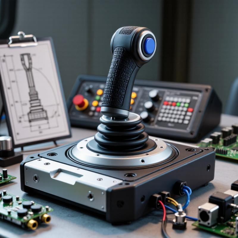
A hydraulic regulation joystick converts hand movement into a controlled command for a valve. Moving it farther can increase spool opening and raise flow, while pressure depends on the load and system settings. Proportional control makes fine adjustments possible. Small movement matters. On an excavator, a careful lever input can help a boom lift smoothly instead of jolting; on a compact machine, it can make slow positioning easier. Yet a 20% lever stroke does not always mean 20% more flow. Spool geometry, oil temperature, and load pressure all influence the result.
MarketsandMarkets’ 2022 hydraulic equipment market report estimated a market value of US$39.5 billion and projected US$51.5 billion by 2027. That forecast reflects broad equipment demand, not joystick performance, so buyers should assess the control itself. Check the joystick’s output type, operating force, deadband, and repeatability against the valve and machine requirements. ISO 4413:2010 provides general safety requirements for hydraulic systems, while ISO 4406:2021 defines a cleanliness coding method for fluid contamination. Clean oil helps protect small control passages. One caveat remains: published specifications cannot replace testing under the machine’s actual load, temperature, and duty cycle. I would verify the response on the equipment, not just on paper.
Technical comparison of common joystick control architectures and practical supplier-evaluation criteria. Specific performance depends on the selected model and hydraulic system.
| Control architecture | Joystick output | Proportional-control method | Typical configuration | Key selection checks |
|---|---|---|---|---|
| Hydraulic pilot joystick | Pilot hydraulic pressure | Lever movement changes pilot pressure; the main control valve uses that signal to meter actuator flow. | Commonly available in single- or dual-axis layouts; port count and operating pattern depend on the model. | Confirm pilot supply and return requirements, pressure range, port layout, hydraulic-fluid compatibility, and valve compatibility. |
| Electrohydraulic joystick | Electrical signal, such as voltage, current, PWM, or a digital bus, as specified for the model | Lever position is converted into an electrical command for a compatible proportional valve or controller. | May include one or more axes, switches, or thumb controls; electrical options vary by configuration. | Match the signal type, supply voltage, connector and pinout, controller input, EMC requirements, and environmental rating. |
| Hybrid joystick system | Combined electrical and hydraulic interfaces, where provided | Electrical commands and hydraulic pilot signals are used according to the system design. | Used when a machine design requires both types of control interface. | Request interface diagrams and confirm that both signal paths are supported by the machine's valves and controls. |
| Two-axis joystick layout | Two independent command axes | Movement along each axis provides a command in either direction; the exact output curve is model-dependent. | Can provide up to four directional commands, subject to the joystick and system design. | Check axis assignment, direction of operation, deadband, output curve, and whether simultaneous axis movement is supported. |
| Neutral-return arrangement | Mechanical return behavior; output depends on the control architecture | A spring-return mechanism commonly brings the lever back to neutral when released; detents or friction options are model-dependent. | Available arrangements vary by application and joystick design. | Confirm return behavior, detent positions, operating force, and the machine's safe-state requirements. |
| Supplier documentation and validation | Model-specific drawings, ratings, wiring or hydraulic diagrams, and test information | Verifies that command output matches the intended valve response and operating range. | Request documentation for the exact ordering configuration. | Review operating temperature, ingress protection, vibration limits, lifecycle information, traceability, warranty, and applicable safety documentation. |